Imagine ordering a custom replacement part for an expensive piece of equipment.
The designer sends over a beautiful 3D model. Every curve looks right. The mounting holes appear perfectly positioned. You approve the file, send it for printing, and expect the replacement part to fit.
Then the physical version arrives.
One hole doesn’t line up. A small clip breaks during assembly. The part looks almost identical to the original, but it can’t do the job it was designed for.
Now you’re dealing with another revision, another production cycle, and another delay.
This is an illustrative scenario, but it highlights an important distinction: a 3D model can look finished without being ready for manufacturing.
And that distinction matters to anyone developing a product, prototyping a component, or outsourcing 3D design work.
Professional 3D modeling for 3D printing is about more than creating a digital shape. It involves designing geometry that works with real materials, manufacturing processes, dimensional requirements, and the way the final object will actually be used.
So how do you know whether your design is truly ready?
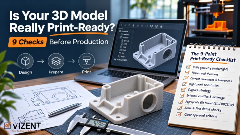
This guide walks through nine practical checks, the mistakes worth catching early, and the information your modeling partner needs before a project goes into production.
What Does “Print-Ready” Actually Mean?
A print-ready 3D model is a digital design that has been prepared and validated against the requirements of its intended 3D printing process.
At a minimum, the geometry should be valid, the dimensions should be correct, and the features should be suitable for the selected material and printer.
For a functional product, that’s only part of the story.
A model can pass a software mesh check and still produce a part that doesn’t fit, cracks under pressure, or needs extensive finishing before it’s usable.
That’s why it’s helpful to separate three questions:
- Can it be printed? Is the geometry technically valid and compatible with the printing process?
- Can it be manufactured reliably? Are the wall thicknesses, supports, clearances, and other features suitable for repeatable production?
- Will the finished part work? Does the printed object meet its intended functional and dimensional requirements?
These are different questions. A good design workflow addresses all three.
For businesses that need help converting a concept or existing reference into manufacturing-ready geometry, Vizent’s 3D Modeling for 3D Printing Services provide a starting point for discussing the design and file preparation requirements.
Before Opening Your Modeling Software, Ask One Question
What is this object supposed to do?
It sounds obvious. Surprisingly, it’s one of the most important questions in the entire workflow.
A decorative tabletop model and an industrial mounting bracket might have similar dimensions, but they need very different design decisions.
A decorative object may prioritize surface detail and appearance. A bracket may need to support a load, fit an existing assembly, and withstand repeated use.
Consider three projects:
Project A: A marketing prototype
A product team needs a physical mock-up for a client presentation. The goal is to communicate appearance, proportions, and overall design. Cosmetic finish matters more than mechanical performance.
Project B: A functional enclosure
An electronics manufacturer needs a housing for a device. It must accommodate internal components, mounting points, cable openings, and a removable cover.
Project C: A replacement component
A maintenance team needs to reproduce a discontinued plastic part. The new design must match critical dimensions and operate within the existing equipment.
All three involve 3D modeling. But applying the same design assumptions to all three would be a mistake.
The intended application influences your software, modeling method, materials, tolerances, and quality checks.
That is why the most useful design brief begins with the purpose of the part, not merely a request to create an STL file.
The 9-Point Print-Ready Checklist
1. Start With the Right Geometry, Not Just the Right Appearance
One of the first things a designer should check is whether the model represents a valid physical object.
In 3D graphics, geometry can sometimes overlap, contain gaps, or consist of surfaces that look correct from the outside but do not define a solid volume.
That can be acceptable for certain visual applications. It becomes a problem when a slicer needs to determine what material belongs inside the object.
For many printing workflows, a model should form a properly closed, manifold solid.
Think of a sealed cardboard box. Its sides form one continuous boundary around the space inside.
Now imagine cutting a hole in the bottom or leaving two panels disconnected. From some angles, the box might still look complete. Structurally, it isn’t.
A similar issue occurs in digital geometry.
What to examine:
- Open edges or missing surfaces
- Unexpected internal geometry
- Overlapping or intersecting bodies
- Incorrect surface normals
- Non-manifold edges
- Separate components that should be combined
Automatic mesh-repair tools can help, but they don’t always understand the designer’s intention. A repair operation may close a hole that was supposed to remain open.
The practical lesson: inspect the repaired geometry rather than assuming a successful repair message means the design is correct.
2. Check Wall Thickness Before You Add More Detail
Thin walls are among the easiest design problems to overlook.
A wall can appear substantial when viewed on a large monitor, yet become fragile or impossible to produce at its intended physical size.
Suppose you’re creating a compact electronic enclosure. The outer shell needs to protect the components, while mounting features and internal supports must survive assembly.
Making every wall thinner may save material, but it could compromise stiffness, durability, or printability.
Making everything thicker isn’t automatically better either. Excessive material can increase weight, build time, and the risk of certain forms of distortion.
The right approach is to understand the requirements of the chosen printing process.
For example, Prusa’s modeling guidance explains how nozzle size and extrusion width affect very thin features in filament printing.
With one commonly described setup using a 0.4 mm nozzle, a single extrusion perimeter is approximately 0.45 mm wide, although the actual result depends on the printer and settings.
That doesn’t mean a 0.45 mm wall is automatically suitable for a functional product.
It simply illustrates why feature dimensions must be considered alongside machine capabilities.
A useful design question: Is this feature merely printable, or does it also need to be strong enough for its intended use?
Those are not the same standard.
3. Design Clearances Around the Real Assembly
Two components can have perfectly matching dimensions in CAD and still fail to fit together after printing.
Why?
Because physical manufacturing involves tolerances.
Imagine you’re designing a removable lid for a plastic enclosure. If the lid and its opening have exactly the same nominal dimensions, the printed components may bind or fail to assemble.
The model needs appropriate clearance based on the printing process, material, orientation, and intended fit.
A sliding component needs different clearance from a press-fit component. A removable lid has different requirements from a hinge intended to remain assembled.
And those requirements can change between printing technologies.
Instead of asking for a generic tolerance, define the intended relationship:
- Should the components slide freely?
- Should they snap together?
- Should the connection be tight but removable?
- Will the parts be assembled repeatedly?
- Are the mating surfaces load-bearing?
Critical dimensions should be identified in the technical drawing or project brief.
For especially important assemblies, printing a small test section can be more informative than repeatedly adjusting the entire product.
4. Think About Print Orientation Before Finalizing the Design
Here’s something that often surprises people new to additive manufacturing:
The same digital model can behave differently depending on how it is positioned during printing.
For filament-based FDM or FFF printing, the orientation of the layers can influence mechanical strength.
A part that must resist force in one direction may perform differently if its critical feature is built across layer interfaces.
Orientation also influences surface appearance, support requirements, and sometimes dimensional accuracy.
Consider a mounting bracket.
If the part is printed in one orientation, the load may act mostly within the printed layers. Rotate the same geometry, and that load may instead encourage separation between layers.
The two prints can look nearly identical.
Their performance may not be.
This is why designers should consider likely forces and intended use before finalizing the model.
Designing for the printer does not mean ignoring the product. It means making the printer work in favor of the product.
5. Avoid Supports That Create More Problems Than They Solve
Supports are temporary structures used to hold selected areas of a model during printing.
They’re useful, and sometimes necessary.
But excessive supports can introduce additional material costs, longer production times, difficult removal, and surface imperfections.
Picture an object with a delicate visible surface suspended over a large unsupported area.
The printer may require supports underneath it. Removing those supports could leave marks exactly where the final product needs a clean finish.
Sometimes the solution isn’t a different printer setting.
It may be better to change the design.
Possible adjustments include reorienting the model, splitting it into components, changing an overhang, or making small geometry modifications.
The right choice depends on whether the product’s dimensions and functionality can accommodate those changes.
The goal isn’t to eliminate every support.
It’s to avoid creating unnecessary manufacturing complications.
6. Don’t Forget Internal Cavities and Trapped Material
Hollowing a model can reduce weight and material consumption.
But a hollow design introduces another question:
How will material get out of the cavity after printing?
For resin-based printing, enclosed hollow features may trap liquid resin or create suction-related problems during manufacturing.
For powder-based printing, unsintered or unfused powder can remain inside hollow sections.
Designing appropriate drainage or powder-escape openings may be necessary.
Their size and placement depend on the process, material, geometry, and cleaning method.
For example, Formlabs’ SLS design guidance discusses powder removal and access requirements for hollow geometries.
A sealed cavity that looks excellent in CAD may create a production or cleaning problem.
That’s why internal features deserve just as much attention as the visible surfaces.
7. Choose the File Format Based on What Happens Next
“Please send the STL.”
It’s a familiar request. But an STL isn’t always the only file a business should receive.
The best deliverable depends on whether the model will simply be printed, modified later, or transferred into another engineering workflow.
| File format | What it’s useful for | Important consideration |
|---|---|---|
| STL | Transferring mesh geometry to widely used printing workflows | Does not inherently define measurement units |
| 3MF | Transferring manufacturing-oriented mesh data and supported metadata | Receiving software must support the relevant features |
| STEP | Exchanging CAD geometry for further engineering or manufacturing preparation | Not a direct substitute for every slicer’s mesh input |
| OBJ | Transferring polygon geometry, including some visual data | May require additional preparation for manufacturing |
| Native CAD file | Editing design features and dimensions in the original software | Requires compatible software and version support |
The distinction between STL and 3MF is particularly important.
STL primarily describes surface geometry. The 3MF Consortium explains how 3MF addresses limitations of traditional STL workflows, including unit and data representation.
For a one-time decorative print, a correctly prepared STL might be sufficient.
For a product that will undergo future revisions, having an editable CAD model can be far more valuable.
A practical recommendation: When you commission custom modeling, clarify whether you need only a printable file or both the printable export and editable source geometry.
That small conversation can prevent a complicated handoff later.
8. Validate Scale, Fine Details, and Manufacturing Limits
A digital model doesn’t tell the complete story until someone confirms its intended physical size.
An object designed in inches but interpreted as millimeters can create an obvious problem.
More subtle issues are equally important.
Small lettering may not remain legible. Narrow slots may close. Fine decorative features may be lost. Small holes may require additional processing to achieve the intended fit.
The printer’s resolution alone doesn’t determine whether these features will be successful.
Material behavior, feature orientation, post-processing, and the manufacturing process all matter.
Before releasing the file, inspect:
Overall size: Does the imported model match the intended physical dimensions?
Critical features: Are holes, pins, connectors, text, and other details large enough to manufacture reliably?
Surface requirements: Have you identified which surfaces must meet a particular visual standard?
Production constraints: Is the design compatible with the chosen machine’s build volume and process capabilities?
HP’s additive manufacturing design guidance demonstrates why details such as wall thickness and feature orientation require technology-specific evaluation.
The point isn’t to memorize a universal minimum measurement.
There isn’t one specification that works for every printer, material, and geometry.
The point is to design against the actual process that will be used.
9. Define What “Approved” Means Before Production
This is arguably the most overlooked check in a business 3D modeling project.
The designer thinks the work is complete because the model looks correct.
The manufacturer thinks the work is complete because the file slices successfully.
The customer thinks the work is complete when the printed component fits and performs its intended function.
Three different definitions of success.
A stronger workflow establishes acceptance criteria before the final file is delivered.
For a functional part, that could include:
- Overall dimensions and critical hole locations
- Assembly-fit requirements
- Permitted deviations on important features
- Material and manufacturing process
- Required surface finish
- Test-print or inspection requirements
- File naming and revision identification
Not every decorative model needs a detailed engineering inspection plan.
But functional components should have clear expectations.
It is much easier to agree on those requirements at the beginning than to negotiate them after a failed production attempt.
FDM, SLA, SLS, or MJF: Why Your Printing Technology Matters
It’s tempting to create one universal design and decide on the printer afterward.
Sometimes that works.
For more demanding projects, the selected technology should influence the design from the start.
| Technology | Where it is often useful | Design considerations |
|---|---|---|
| FDM / FFF | Functional prototypes, fixtures, housings | Layer direction, nozzle-dependent features, overhang supports |
| SLA | Detailed prototypes, smooth-surface models | Resin supports, orientation, drainage and post-curing |
| SLS | Complex polymer components and functional geometries | Powder removal, clearances, thermal behavior |
| MJF | Functional polymer parts and production-oriented applications | Feature dimensions, powder removal, process-specific tolerances |
For example, an object with a complex internal channel might be difficult to produce with certain support-dependent processes. A powder-bed process may offer a more suitable approach, although the channel must still allow powder removal.
Likewise, a highly detailed decorative object might benefit from a resin process, but that doesn’t automatically make it the best choice for a component exposed to repeated mechanical stress.
The correct decision depends on the product, material requirements, production quantity, cost, and equipment availability.
If the printing technology hasn’t been selected, the modeling team should know that.
Otherwise, the design may need significant changes later.
A Practical Example: Turning a Replacement Housing Into a Printable Model
Let’s make this more concrete.
Imagine a company needs a replacement housing for a small electronic device.
The original housing is damaged. The manufacturer no longer supplies the component. The business has the physical sample and several photographs, but no editable CAD file.
This is a hypothetical example to illustrate a sensible project workflow, not a documented Vizent customer case.
First: Capture the Geometry
A designer needs more than photographs to reproduce functional dimensions accurately.
The process might involve measuring the original housing, reviewing its mounting locations, collecting images from multiple angles, and using scan data where suitable.
Photos can help establish shape and appearance.
They cannot reliably reveal every hidden dimension or internal feature on their own.
Second: Identify What Must Stay Accurate
Not every curve on the housing is equally important.
The outer appearance may allow some flexibility, while screw-hole locations, connector openings, and internal clearances could be critical.
These features should be measured and identified before the design is finalized.
Third: Build the Editable Model
A parametric CAD workflow may be appropriate because the design has dimension-driven features that could require revision.
The designer can model the shell, mounting bosses, openings, and joining features as controlled geometry.
Fourth: Review Manufacturing Feasibility
Now the team examines wall thickness, assembly clearances, likely print orientation, and areas requiring support.
A small adjustment to a mounting boss or enclosure wall may improve manufacturing feasibility without changing the product’s essential function.
Fifth: Validate Before Releasing the Full Design
Instead of assuming the first complete print will fit perfectly, the team may test a critical mounting feature or print a prototype housing.
Measurements and physical fit checks provide feedback for revisions.
Finally: Deliver the Right Files
The customer receives the agreed files, which might include an editable CAD source, STEP geometry, a printable export, and a revision record.
The important deliverable isn’t simply a file that opens.
It’s a design package that supports the next stage of work.
What If You Don’t Have an Existing CAD File?
Many businesses assume they need an existing 3D model before contacting a modeling company.
That isn’t necessarily the case.
The information available at the beginning of a project can take several forms.
| What you have | How a modeling project may begin |
|---|---|
| Hand sketches with dimensions | Develop geometry from the supplied design references |
| Engineering drawings | Reconstruct the intended part using technical dimensions |
| Existing CAD files | Review, modify, or prepare geometry for manufacturing |
| A physical component | Measure or scan the object and develop a digital model |
| Photographs | Establish visible geometry, then obtain missing dimensions |
| STL or OBJ files | Inspect, repair, or rebuild geometry where appropriate |
A physical reference can be particularly valuable for replacement parts or reverse engineering.
But there is an important limitation: a model generated from an image or surface scan may still require additional engineering information to reproduce precise functional details.
Don’t confuse visual similarity with dimensional certainty.
A reliable provider should identify which measurements are known, which are estimated, and which need confirmation before manufacturing.
The Hidden Cost of a Cheap 3D Model
When businesses compare 3D modeling services, price is naturally part of the decision.
But the cheapest modeling quotation isn’t necessarily the lowest-cost route to a finished product.
Consider a project where one provider offers only a basic mesh, while another includes editable CAD files, geometry validation, and a defined revision process.
The first quotation may appear more attractive.
However, if the model needs substantial rework before printing, those additional costs can change the comparison.
The relevant costs may include:
Initial modeling: Creating or reconstructing the geometry.
Manufacturing preparation: Checking geometry, dimensions, supports, and relevant process constraints.
Revisions: Correcting the design after review or testing.
Prototype production: Printing and inspecting trial components.
Communication: Resolving incomplete requirements or incompatible files.
This doesn’t mean every project needs an expensive, full-service workflow.
A simple decorative model may require relatively little technical preparation.
A precision replacement part may justify more extensive validation.
The goal is to pay for the work your project actually requires—and understand what’s included before production begins.
How to Brief a 3D Modeling Company Without Missing Critical Details
A good brief can save more time than a long series of emails after work begins.
If you’re requesting professional 3D modeling for a printing project, the following structure is a useful starting point.
Example Project Brief
Project: Custom replacement housing for an electronic device
Purpose: Produce a functional prototype for assembly testing
Available references: Existing housing, photographs, and dimensioned sketches
Material requirements: To be confirmed based on operating conditions
Critical features: Mounting-hole locations, connector openings, enclosure fit, removable cover
Printing process: To be selected in consultation with the manufacturer
Required files: Editable CAD source, STEP, and a suitable printable export
Quality requirements: Correct overall dimensions, validated assembly fit, and review of print-critical features
Revision expectations: Initial design review, agreed revisions, and final approved version
Timeline: Target design delivery date and expected prototype testing schedule
This type of brief gives a modeling provider a much clearer understanding of the job than a message saying, “I need a 3D printable model. Please share your price.”
It also helps the provider explain which requirements can be met from the available references and which need additional technical input.
How Do You Choose a 3D Modeling Partner?
A portfolio is useful, but attractive images alone don’t tell you how well a company handles manufacturing constraints.
For a printing-focused project, ask questions that reveal how the team works.
Can you build the model from my existing references?
This matters if you only have drawings, photographs, or physical samples.
Will I receive editable files?
You may need the design again for modifications, future product versions, or another manufacturing process.
How do you check printability?
Ask whether the workflow includes appropriate geometry checks, scale verification, and review of relevant manufacturing features.
How are revisions handled?
Clarify what happens if the initial design needs changes after a technical review or prototype test.
Who is responsible for physical validation?
A modeling company and a printing manufacturer may have different responsibilities. Determine who will assess the final printed part against its intended requirements.
How will the design be handed over?
Agree on file types, versions, critical dimensions, and any supporting documentation.
A dependable working relationship is built on clear scope and communication, not just a promise of quick delivery.
Where Vizent Fits Into the Process
Every 3D printing project starts from a different place.
Some clients have detailed CAD files and need modifications. Others have a physical reference, a collection of photographs, or a concept that has yet to become a complete digital design.
Vizent’s 3D Modeling for 3D Printing offering addresses digital model development, custom designs, prototype preparation, and reverse engineering requirements.
Its service description also covers working with different reference materials and preparing files in formats such as STL, OBJ, and STEP.
For businesses exploring an outsourced modeling workflow, the useful first step is to share the intended application, existing references, critical dimensions, and expected deliverables.
That creates a basis for evaluating project scope and determining the appropriate modeling approach before work begins.
It’s also worth clarifying the division of responsibility between digital modeling and any physical manufacturing or testing that follows.
Frequently Asked Questions – 3D modeling for 3D printing
Can you turn a photograph into a 3D printable model?
Yes, photographs can be used as references for creating a 3D model. However, accurate functional components often require additional dimensions, multiple views, or physical measurements. A photograph alone cannot reliably reveal all hidden geometry.
Is an STL file enough for professional 3D printing?
An STL can be sufficient for many printing workflows if its geometry and scale are correct and the model is appropriate for the process. Businesses planning future revisions may also need editable CAD geometry and technical drawings.
How do I know if my 3D model is watertight?
Mesh inspection tools can identify problems such as open boundaries and non-manifold geometry. The model should also be checked in suitable slicing or preparation software. Passing a mesh check does not guarantee that the printed object will satisfy its intended function.
Can a 3D model designed for animation be used for 3D printing?
Sometimes, but it may need substantial preparation. Animation models can include separate surfaces, thin details, internal intersections, and geometry created primarily for appearance. These features may need to be modified before manufacturing.
What affects the cost of 3D modeling for 3D printing?
The main factors include geometry complexity, dimensional requirements, available references, the need for reverse engineering, manufacturing preparation, revisions, and required deliverables. A reliable quotation should reflect the actual scope.
Does a print-ready model guarantee a successful print?
No. A well-prepared model reduces design-related risks, but the final outcome also depends on machine condition, material quality, process settings, operator decisions, and post-processing. Functional parts may still require testing and validation.
Final Thoughts: A Good 3D Model Should Survive Contact With Reality
A digital model is easy to admire.
You can rotate it, zoom in on its details, and present it from an ideal angle.
But a manufactured object has to do something more demanding.
It has to occupy physical space. It has to fit. It has to survive handling, assembly, or use. And it has to be produced using a process with real limitations.
That’s where thoughtful 3D modeling earns its value.
The most successful projects don’t treat print preparation as an afterthought. They consider manufacturing requirements while the design is still being developed, when adjustments are easier to make and less disruptive.
Whether you’re developing a new product, reproducing a replacement component, or turning an idea into a working prototype, start with the outcome you need.
Then design toward it.
Have a 3D Printing Project in Mind?
You don’t necessarily need a finished CAD file to begin the conversation.
If you have a sketch, an existing component, engineering drawings, or a product concept, explore Vizent’s 3D Modeling for 3D Printing Services.
Share your references, intended application, and required deliverables through the Vizent contact page to discuss the scope of your modeling project.

CEO & MD
The CEO and Managing Director at Vizent Solutions, Bigyan Kar, leads a team of talented technology professionals who excel in the development and implementation of next-generation 3D visualization solutions for the following areas: gaming, architecture, AR/VR, CAD, and interactive simulations. Through his knowledge of digital design and technology, as well as his commitment to providing the highest level of immersive, accurate, and reliable 3D experiences for its clients, Vizent is constantly innovating and pushing the boundaries of the 3D modeling and visual storytelling industries.